New polar alignment is easier with measuring 2. – extended version
Dear Amateur Astronomer and Potential Astronomer Colleagues,
As well known, a lot of information has already been written about polar alignment and King-type polar photographs so far in the internet. In this material, I would like to share both my practical knowledge with you acquired in this field to make your similar activity easier and, also my experiences regarding reparation of the technical problems of my telescopes.
I need to apologize in this way, especially in case of young amateurs, since I communicated my previous blog called “It is easier with measuring” without any preliminary explanations; although it has been viewed more than one thousand times, frequently by them.
This written information below will help everyone applying the technology of “It is easier with measuring” and, in this way, it will make the polar scope which is used for mobile telescopes unnecessary (which is, in my opinion, unusable and inaccurate).
Problems of polar scopes:
- The reticle of several polar scopes has been calibrated roughly 20-25 years ago – the exact location of Polaris has been changed since that time
- It is necessary to collimate the optical axis of the polar scope and the rotational axis of the RA shaft of the equatorial mount of the telescope very precisely
- During the setting up process of the polar scope based polar alignment, it necessary to adjust the right position of the polar scope (reticle) rotating it within the hollow shaft as far as the Big Bear (UMa) will be seen in the same position looking at its stars in and out of the polar scope ROUGHLY (or in estimated accuracy…)
Before polar alignment procedure, I highly recommend putting flat stone pieces to the ground under the tripod-legs and levelling of the horizontal platform of the equatorial mount.
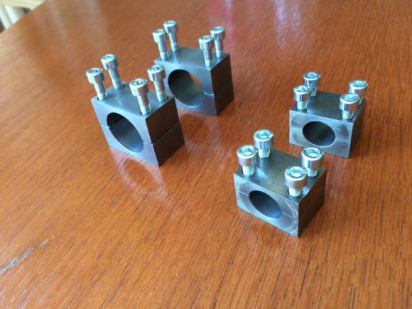
The legs of the NEQ6 mount consists of two tubes which has remarkable play; therefore, the previously and precisely aligned position of the mount will be misaligned if you flip the scope. So, avoiding this kind of problem I have designed and produced three metal rods for stressing the legs out (see figure 1.b) as much as possible.
First steps
If you have purchased an astronomical telescope (no matter what type and diameter is), you may want to use it of course. My advices written below will help you during your very first steps.
With your scope, you will need to buy a green laser pointer as well (red one is not bright enough in the night sky) together with a holder unit which can continuously provide rigid position for the laser pointer parallelly with the optical axis of the scope. Using the two times three adjustment screws of the laser holder unit, please collimate the laser beam and the telescope optical axis. This laser indicator beam will be extremely useful later, in every case as soon as you will need to aim the scope onto any celestial target in the night sky (see figure 1.a).
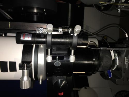
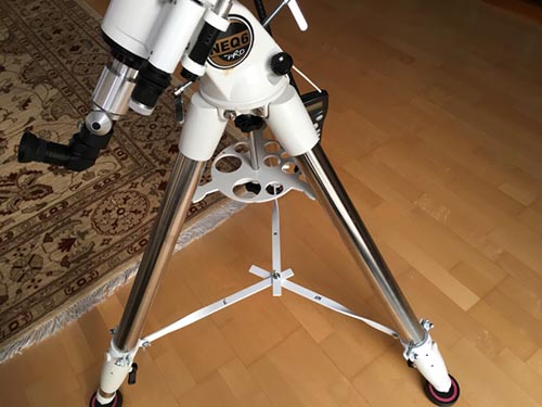
[Figure 1.a] Laser pointer fixed in the right position [Figure 1.b] Strengthen NEQ6 mount tripod
You can collimate the telescope’s optical axis and the green light beam of the laser pointer properly fixed onto the tube if you sight a bright star in the center of the telescope’s (reticle) eyepiece using the hand controller buttons of the mount or manually moving it to the right position above. If it is has done, you just need to move the position of the laser beam onto the certain star accurately.
Telescope Focusing
This very important and sensitive process. Usually, there is no any adjusted element on a brand-new telescope purchased from a store (especially, purchased from a web-shop), so I highly recommend using the big and bright Moon as first target for focusing. The best first approach is to find the edge of the Moon and use it for focusing.
The next level of focusing (as soon as you can see stars in the field of view of the eyepiece) is to rotate the focus knob back and force periodically but by smaller and smaller amount of rotation while you can see the smallest diameter stars with the brightest pin’s points.
If you want to make nice shots about deep sky objects using your telescope, you will need more accurate focusing. I propose buying and using so called “Bathinov Mask” (figure 2) fitting the external diameter of your telescope tube. Please, using the three small legs at the edge of the mask apply it onto the front hole of the tube; then you will see a special colorful pattern on the display of the camera. There will be an oval bright form in the center of 2×3 pin-like X-shaped pattern (figure 3).
Using (rotating back and force) the above mentioned focusing knob (or its micro-focusing gear if it has) please try to achieve the absolute symmetrical position looking at the X-shape above. As soon as you could achieve the optimal position, please fix the focusing mechanism and do not forget to remove the Bathinov-Mask!!!


[Figure 2] [Figure 3]
Polar Alignment
Well, the next step is the most difficult part of the whole adjustment procedure: polar alignment by adjusting the mount in extremely fine movement-steps and testing the result by King-type photographs. To be honest, I struggled a lot for more than one and a half years (but not just me…).
I have already shared these kinds of results of mine in my previous material called “It is easier with measuring”. If you follow the instructions written in that paper, you will be able to produce very accurate polar alignment (see at the end of this document).
Let’s start now!
Wait for a clear and starry night. Please adjust the right ascension shaft of the mount to roughly 47° based on the scale at the side of the mount or any other way and turn the declination shaft horizontal position. Look for the star called Polaris which can be found around 47° elevation in North. You can find Polaris if you imagine a straight line between the two brightest stars of Ursa Major (Alpha and Beta UMa, called Dubhe and Merak) and extend this line beyond Dubhe and measure the distance of Dubhe-Merak five times to this extension. Polaris must be somewhere there.
You will use the green laser pointer first time now which has been paralyzed to the telescope’s optical axis previously. Moving your scope, please adjust the green laser beam next to the Polaris by 1.5x Moon-diameter (roughly 0,45”), in the position where Polaris, the “end-point” of the laser beam and Kochab (Beta UMi) can be seen in one straight line. In this moment, you could achieve your telescope points to the pole (more or less), which is the rotational center of the North sky.
Set the exposure time of your DSLR or astronomical CCD camera, fixed to the bottom of your telescope rigidly enough, to ‘M’ (manual) position.
In case of King-photograph, it is highly recommended to move the rotational center of the sky (explained above) to the center of the field of view of the camera.
Take a 2 times 5-minute picture at first on the following way:
- start the exposure (open shutter) with tracking telescope and wait 5 minutes,
- stop the clock-drive (but the camera shutter remains open)
- wait another 5 minutes and close the shutter.
Congratulation, this is your very first King-photograph!
I would like to write about the “mysterious King-photography” below how easy it is, in fact.
If you analyze a King photograph of a well aligned mount, in ideal case, you will need to find arcs drawn around the rotational center of the Earth and pinpoint-like stars sitting at the end of these arcs. These arcs must arrive exactly to the center of the stars. If your picture is not like this, do not worry; sooner or later you will have this one.
From the viewpoint of the adjustment, the important detail is the relative position of the arcs and the stars. If the polar position of the mount is far from the ideal position, you will see short straight lines (instead of points) at the end of the arcs like hoes or patterns like number “1”.
If these short straight lines are in horizontal position, you will need to modify the elevation of the RA shaft.
If these short straight lines are in vertical position, you will need to modify the horizontal platform of the mount.
Usually, I begin this process with elevation adjustment and as soon as the elevation position seems to be okay I deal with horizontal position as well. After each iteration step above, it is necessary to check the real effect of the actual modification taking a King photograph. When the real position is far from the target then 2×5 minutes King-shot is enough; but as soon as the difference (the error of the polar position of the RA shaft) is better and better, the length of straight line at the end of the arcs become shorter and shorter. So longer and longer exposure time (2×10 and 2×20 minutes) will be necessary to follow the real situation achieving higher and higher accuracy in this way.
I start the elevation adjustment process with rotating the elevation adjustment screw after releasing the fixing screws on the left and right sides of the mount. I check the accuracy of the polar position after every screw-rotating step taking a King photograph with max ISO 100-200 sensitivity. When tracking is on, the stars will draw point-spread structures or, if the position is not okay yet, short straight lines. After 5 minutes, when the tracking is off (but the shutter remains opened, during the second half of the King shot) the stars will draw small arcs because of the rotation of the sky in front of the telescope being at a standstill position. Now I check and analyze the figure of the star-trails. If the arcs do not join exactly to the center of the dots, or there are horizontal lines (“hoes”) instead of dots, I adjust the 47° elevator adjustment screw (altitude) in one direction and I check the result using a new King shot again. If the error is increasing I need to reverse the direction of the adjustment and follow this process until the error eliminates, and the arcs start from the center of the dots.
This method must be used for horizontal adjustment as well; the only difference is the direction of the pointing error in the King shot: you need to find the vertical component of the short straight lines or the vertical joining difference of the arcs and the dots. Additionally, you need to rotate the horizontal platform of the mount of course, using the horizontal position adjustment screws until the arcs join exactly to the center of the dots.
If the result seems to be okay using 5+5 minutes King photographs, you can switch to 10+10 minutes exposures and, later, I suggest using 20+20 minutes King shots (figure 4). In this way the polar position of your mount will be more and more accurate.
Tighten down the fixing screws after each iteration step!
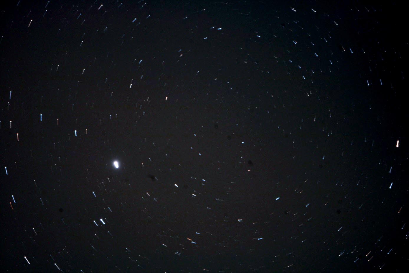
[Figure 4] Correct King photograph (8,5 + 8,5 minutes)
Repairing technical problems
My very first telescope was a Newton reflector (250/1000mm) on an NEQ6 equatorial mount having several mechanical problems.
Every fit had remarkable play, I have manufactured new shaft, the vertical adjustment screws have been too long, buckled and it was not possible to use them. I disassembled the mount and I created a new chunk for the adjustment screws in closer position.
I realized that the fixing of the primary mirror is very sensitive: if I tightened the fixing screws too much then the mirror distorted, but if I did not tight these screws enough, the mirror had remarkable lateral slackness. My biggest problem with this tube was the winter collimation: as soon as the temperature has dropped below minus 5 or 10 degrees Celsius, the star images degraded remarkably. The secondary mirror has been glued onto its metal holder plate using very rigid adhesive material in the factory, so the thermal dilatation distorted the surface of the flat secondary mirror during cold winter nights. This can be repaired only by removing the glass very carefully and re-glue it, using much more elastic adhesive material which can keep its elasticity at low temperatures as well.
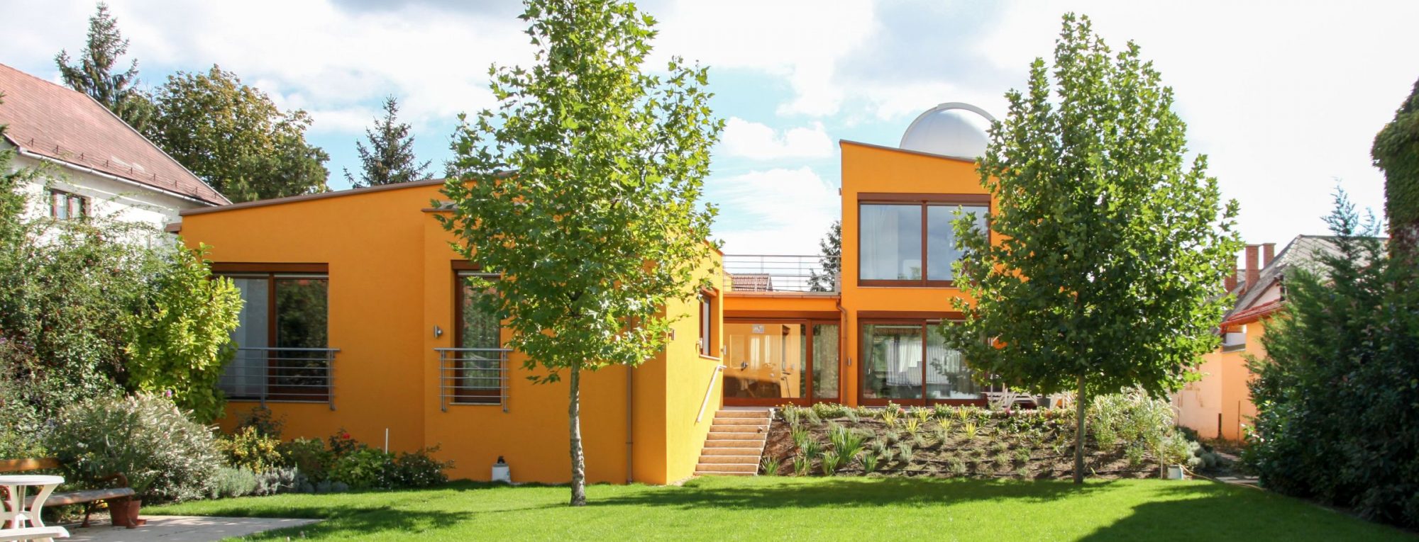
My very old intention and desire has become true when I could build a dome onto the top of my new house and could install new telescopes under my dome. Today’s situation was evolving during a continuous development process: now I have a Fornax-152 mount with three telescopes on a declination platform: 100/550 SkyWatcher APO with field flattener, 185/1300 CFF Telescopes APO with field flattener and 14”/F10 LX200 ACF Meade with 6,2x Optec Lepus focus reducer (2500mm focal length). As the list shows above, there are very different telescopes on the same platform which meant several optical and mechanical problems.
There are Canon 750D cameras installed on each telescope above (figure 5).
I use the telescopes on the equatorial mount on remote controlled way, from my observer room.
I paralyzed all the three telescopes very accurately, using the live view mode of the cameras with max zoom position.
During horizontal polar alignment process, I have realized when the result of Meade telescope’s King shot became almost perfect then the star image at the top of the arc-trail was on the right side of the arc. It would have been adjusted a little bit more but in the 185/1300 APO’s field the star image was on the opposite side of the arc, on the left. I thought if these two telescopes installed onto the same declination platform, it cannot be true… But, unfortunately, it was true! After some thinking I realized that I did not make paralyzing of Meade and CFF APO accurately enough, therefore I made this paralyzing process again, but much more accurately, using the maximum zoom window of my 750D cameras. After this job, I could absolutely eliminate the problem above and the “different-direction King-errors” have been terminated, the King-shots became excellent in each telescope.
The study, equipping, repairing and development of my telescopes and mount needed one year and I could acquire a lot of experiences during this period which I would like to share my astronomer colleagues here.
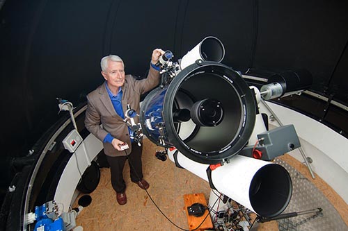
[Figure 5] My telescopes
My Dear Reader, I think a logical question will come up in your head: why a man, an astronomer wants to have three very different size and type of paralyzed instruments and to work with them in the same time? The smaller or larger details of an object, which remained hided, will be obviously visible exposing them in the same time with all the three telescopes. The best of the bests would be if I could catch a star-explosion or other celestial event in the sky.
Let these pictures talk without more words:
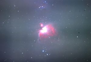
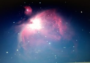
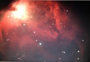
[M42 APO 100/550] [M42 APO 185/1300] [M42 MEADE 355/2500]

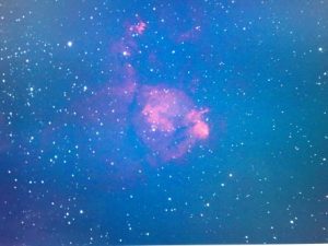
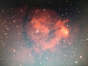
[NGC896 APO100/550] [NGC896 APO185/1300] [NGC896 MEADE 355/2500]
There shots just raw pictures, provided just because of representing my opportunities.
I had the most problems with Meade telescope which I needed to disassemble, repair and assemble again three times in the beginning. The star-image was bad and elongated after goto/slew process (see figure 7).
I assumed if the long focus Meade LX200 ACF provides good picture with roundish star-images then the two APOs with shorter focal distances have to be excellent.
So, my most important task was to achieve perfect polar alignment of Meade.
Solutions:
- The cable of the Canon 750D camera has been spanned after slewing so I needed to release it. The lens bayonet adapter of the Canon 750D had huge play or slackness (roughly 0,3mm in diameter) and the blocking pin has also remarkable slackness. I could eliminate these problems using a rubber O-ring pressed into the gap of the adapter by a fastening clamp. The bayonet play problem has been terminated after this modification.
- Unfortunately, after the solution described in the point above, I have still seen oval star-images in the Meade telescope. I could learn interesting experience during searching the cause of the problem. If there is any kind of slackness (e.g. mirror tilting or mechanical flexure) in the system, the influence of that problem must be stopped after a few time or 3-5 shots (achieving the limitation of the certain play or slackness). If it is not terminated, and we can see oval stars in the whole field of view and in one direction continuously, then the error is continuous, and, in this case, the reason of this problem can be tracking rate error or polar misalignment. In my case, the tracking rate error has been excluded since the Telescope Drive Master has kept the telescope RA shaft rotation on correct rate accurately. It means the polar alignment was not perfect! What a small error could not be seen in the shorter focal distance APO refractors, the same tracking error could be seen in the long focal Meade field.
I have tried to increase the accuracy of the polar alignment in several ways: Scheiner method, PHD guiding, etc.
But I could not achieve necessary polar alignment accuracy for the 2500mm focal distance Meade telescope even using the newest Pole Master system.
This is why, I applied my method written in the “It is easier with measuring” paper and could achieve much better polar position and could take pictures with absolutely roundish stars with Meade telescope as well. It was worth!!! (See figure 8)
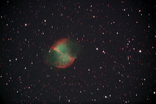
[Figure 7]
Before: wrong position, M27 MEADE 355/2500, 300s/ISO800
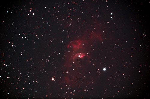
[Figure 8]
Corrected: NGC7635, MEADE 355/2500, 300s/ISO1600 raw, in cloudy sky
Polar alignment is easier with measuring
The accurate polar alignment of any equatorial mount is crucial precondition in astronomical photography for creating pinpoint star images in the picture. This is also important using auto-guider since the control algorithm of the auto-guider system can achieve better result if it does not have to interfere and has to modify the control speed more rarely. Additionally, the accuracy of the GoTo movements of the telescope (so called “pointing error”) will be more accurate after correct polar alignment.
As well known, for achieving accurate alignment of the mount, it is necessary to adjust both the altitude and the horizontal position of the RA shaft as accurately as possible, parallelly with the rotational axis of the Earth. For very precise tracking result, the rotational axis of the RA shaft has to point to the refracted location of the pole. This is slightly different (due to atmospheric refraction) compared to the real rotational axis but in this way the tracking accuracy will be better in the average of the whole sky.
The appropriate adjustment of the refracted pole position can be aligned and tested by King photograph.
This description (how to do it) has been explained in the Meteor magazine several times so I will save the reader from this long explanation now. At the same time, the practical adjustment activity can be extremely difficult and fumbling in case of every mount; although the more expensive and better-quality mounts (like Astro-Physics) provide much more precise and more sophisticated adjustment hardware, so it is much easier to move these mounts in tiny steps during polar alignment activity.
During the adjustment process above, in the beginning, where the mount position is far from the desired accuracy, you can move the mount with higher steps, and when you are closer and closer to the pole, you will need to adjust the RA shaft position with extremely small steps. I did these modifications in estimated way so far; I knew what the right adjustment directions is, but I did not know “how much” I need to rotate the screw. Moreover, the pitch of the screw-thread was too high so it was very difficult to adjust it: just a tiny rotation of the alignment screw modified the position of the RA shaft “dramatically”. Since I did not have time to make new screws, I needed to find new solution to this problem.
If I am not able to move (rotate) the screws in the smallest scales, I will need to measure it at least how much I moved the adjustment screw. This is very important because it is much more time efficient to achieve the final position by 3 King-shots only than 25 King-shots during alignment procedure. (If you are close to the pole you need to apply 15-20 minutes total exposure time for very accurate result.)
So, the task is to make a test system for measuring the smallest rotation of the adjustment screws. Since I needed to measure rotational movement, I put a pointer to the rotating screw and a scale (measuring band) to the stationery parts of the mount. Regarding accuracy, the length of the pointer is the key since the accuracy will be proportional to its length. Using the fixed scale you can measure the rotation of the adjustment screw in both direction without hysteresis so it can be proportional to the position-modification of the RA shaft (which can be calculated based on the King photograph). Additionally, the magnitude and the direction of the next adjustment can be extrapolated based on the previously measured movement and its result calculated from King-shot, which remarkably shortened the full procedure in time.
On the pictures below you can see, how easy and simple is the solution of the polar alignment problem. Simple way for best result!

Measuring Altitude adjustment
Clamps for fixing the mechanical pointers

Measuring the Horizontal (Azimut) adjustment (picture taken from left side)

Measuring the Horizontal (Azimut) adjustment (picture taken from right side)
My Results Against Local Light Pollution
Dear Beginner and Advanced Astronomer Colleagues,
I am an amateur astronomer for several years living in one of the external districts of Budapest, Hungary. I take astro-photographs about, first of all, deep sky objects using DSLR cameras from my rotating dome. I had always problems with the effect of moonlight and street lightning. Street lightning is always problem in Hungarian cities, especially in Budapest. This phenomenon disturbs each amateur astronomer, including me, so for improving this situation I have devised a few solutions explained below.
Creating a good relationship with the streetlight maintenance company, I could achieve removing the huge bulb envelopes from the street lamps in my neighborhood (from 25pcs in all). Therefore, these lamps give light downward only and the lightness of the streets also became remarkably better. In this way, the public and private interests could meet with mutual benefits. My opportunities regarding exposition have improved dramatically: I could immediately increase exposure time by 2x in general. (During astronomical exposures it is extremely important to apply long exposure time for collecting as many photons as I can from the target object but avoiding too high backlight.)
In case of my LX200ACF telescope, the very first optical element of the telescope can be found in the front-ring of the tube. According to my experiences, I could take excellent pictures using my two apochromatic refracting telescopes (185/1300 & 100/550) mounted immediately next to the Meade tube but the photographs taken by Meade always had a reddish background from edge to edge.
This red light-fog is generally originated from the street light.
This is why, although there is no this kind of genuine component for my Meade OTA, I have made a DIY dew-cap shield or sun-shield onto the front ring of the tube, based on my design, according to the small room in my dome.
The test was successful; the reddish veil mentioned above has disappeared from the very pictures taken after this mod.
Realizing such a nice improvement and becoming enthusiastic based on this experience, I have extended the dew shields of my two APO refractors as well (see fig#1). The result was nearly the same; I could achieve better (darker) background in my pictures and can make better deep sky photographs in these cases as well.
I recommend the above mentioned, described and tested solution for both beginner and advanced amateur astronomers. This device can be made for any diameter telescope, and helps not just observatory instruments but it is useful in case of field astronomy as well and will improve the quality of the photographs.
New Idea: 1 picture from 1 shoot!
Dear Beginner and Advanced Astronomer Colleagues,
The new movie called „Csillagnézők” (in English: Star Watchers) has been presented in very first time in the ceremonial hall of the Hungarian Scientific Academy in Budapest on 19/02/2018.
In this movie, beyond the presentation of the history of the Hungarian amateur astronomer organization, amateur astronomer colleagues have presented the telescopes and other equipment of their own which have been constructed and build (or purchased) by them and their astro-photographs.
The most important message of this film was to call Hungarian youngsters’ attention to look up to the sky including its wonderful objects, instead of browsing on video screens all day: “The starry night is for everyone”.
Astrophotography has been developed incredibly during last decades; today, it is possible to take almost as nice and colorful pictures from the surface of the Earth as Hubble satellite telescope can do it from the space. But for making such a nice astro-photographs you need special and pricey instruments, special filters, well based knowledge and experiences. You must take 10 … 50 pictures from the same object using exposures as long as 2-5-10 minute one by one, exact calibration process and, afterwards, a lot of post-processing activity. Additionally, in most cases, the result will be garish, over-saturated and over-sharpened.
A young and/or beginner astro-photographer would have to start his/her activity on much easier way and later, having a lot of experiences acquired in this field day by day, he/she will be able to create wonderful and better pictures about exotic and very dim objects of the night sky than today’s maters… So, if this beginner can make a really good photograph as just a single shot, he/she will take a giant leap forward. A nice single exposure taken by me can give gladness to me today as well…
This is why, I thought we would need to start at the beginning. If you look at the starry sky above, you can see spectacular forms of stars and other objects and a keen-eyed observer can also realize their colors. If you want to photograph them, just a simple and cheap still-camera or mobile phone camera on top of a tripod can be enough, which will be good together with a small astronomy telescope later, and you will be able to look at your pictures on a PC-screen. It is really great fun to see your own astronomy photographs!!!
When buying a new telescope one can get a lot of information just from one photo, about what kind of possibilities can have with a telescope! for example: diagonal, collimation error, mirror or optical distortion, contamination, chromatic aberration, spherical aberration, pixel defects.
New tip: 1 picture – 1 exposure!
Look at the sky using your astro-photo equipment, click one (take one exposure) and please, send us this picture without any modification.
I wish you clear, starry sky to do this and successful pictures with natural color.